
 Jane and John's RV pages
John goes gadget crazy (again!)
12/2016 - added a 'fix' if your ecobee reboots when gas heat is called
Let's get started installing the Ecobee Si
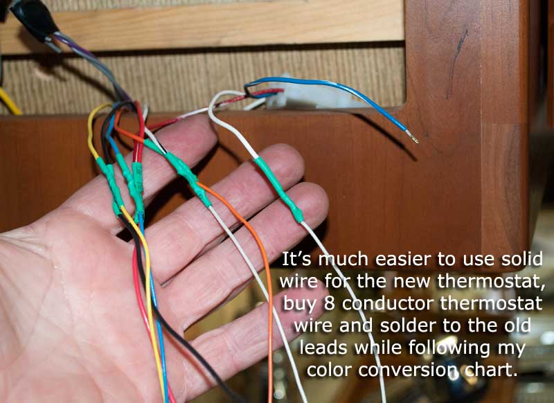
Right off the bat, here's a chart/matrix/truth table you will need when you wire the Si up and to help understand what's going on. I recommend you cut the wires off the back of the Coleman-Mach thermostat and solder solid thermostat wire to the stranded wire, otherwise it's very difficult to push the stranded wires into the Ecobee terminal strip. Those connectors were designed for solid wire! (Yes, you can tin the stranded wire but it's still a hassle to try that.)
Note: CM - Coleman Mach, Si - Ecobee Si wiring, CM condition refers to what leads go high for the various modes with the original Coleman-Mach thermostat - this is the "truth table" part of the chart and it helps understand what's going on with the original thermostat. No potential in the chart means a "dry" lead that has no voltage on it.
| CM connector |
CM colors | Si colors (my wiring) |
CM function & condition>> |
CM off | CM cool | CM electric heat |
CM gas heat |
|---|---|---|---|---|---|---|---|
P1-1 |
red/white | red (note 1) | +12V source | +12V | +12V | +12V | +12V |
| P1-2 | blue/white | blue (note 2) | ground (-12V) | ground | ground | ground | ground |
| P1-3 | white | white | gas furnace (W2) | no potential | no potential | no potential | +12V |
| P2-1 | gray | (note 3) | freeze switch | n/a | n/a | n/a | n/a |
| P2-2 | red | (note 1) | +12V to heat pump | +12V | +12V | +12V | +12V |
| P2-3 | gray | (note 3) | freeze switch | n/a | n/a | n/a | n/a |
| P2-4 | blue | blue | ground (-12V) | ground | ground | ground | ground |
| P2-5 | yellow | yellow | compressor 1 (Y1) | no potential | +12V | no potential (note 5) |
no potential |
| P2-6 | orange | orange | compressor 2 (Y2) | no potential | +12V if 2nd stage called |
no potential (note 5) |
no potential |
| P2-7 | black | green | fan high speed | +12V if fan switch on |
+12V | no potential | no potential |
| P2-8 | white/black | brown | electric heat (W1) | no potential | no potential | +12V | no potential |
| P2-9 | purple | (note 4) | fan low speed | n/a | n/a | n/a | n/a |
Note 1 - the red/white wire from connector P1-1 is the source of +12 volts that powers the thermostat and then gets sent out to the various leads to the RVP heat pump control board. I connected the red/white wire from P1-1 to the red wire from P2-2, and soldered those two wires to the red solid wire that goes to either RH or RC on the Si. This will make more sense later.
Note 2 - the blue/white wire from connector P1-2 is ground and I connected it to the blue wire from connector P2-4 (also ground) and soldered it to the solid conductor blue wire that goes to the "C" terminal on the Si.
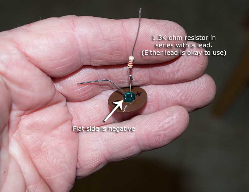
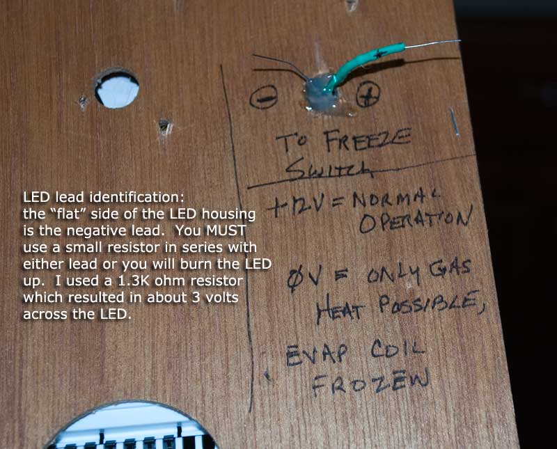
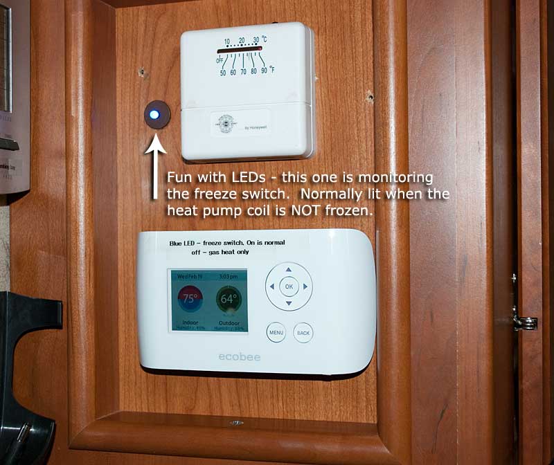
Note 3 - the gray wires are normally closed dry contacts from the control board on the heat pump. I got fancy and installed a blue LED light to indicate when the evap coil was NOT frozen up, i.e., normal heat pump operation. If you want to do the same, get an LED and a 1.2K (or so) resistor and place in series with the gray wires and a source of 12 volts.
Note 4 - the purple wire is for fan low speed. I have never (on purpose anyway) set the fan to low speed, if you want to wire in a separate switch for fan low, knock yerself out ;-) I assume for fan low you apply +12V to this wire and remove +12V from white/black wire on connector P2-7, but that's just an educated guess.
Note 5 - this is not a mistake! Y1 and Y2 are NOT called in the electric heat mode. For electric heat, all the heat pump control board wants to see is +12V on the white/black wire in connector P2-8. This is the reason why you have to set up the Si as two stage cool and two stage heat and not as a heat pump! Then heat stage 1 will be the two compressors operating (and the reversing valve) like in a heat pump but heat stage two is GAS heat. No, you won't be able to manually select gas heat from the Si user interface, just a minor drawback.
Time for my favorite part - the pictures!
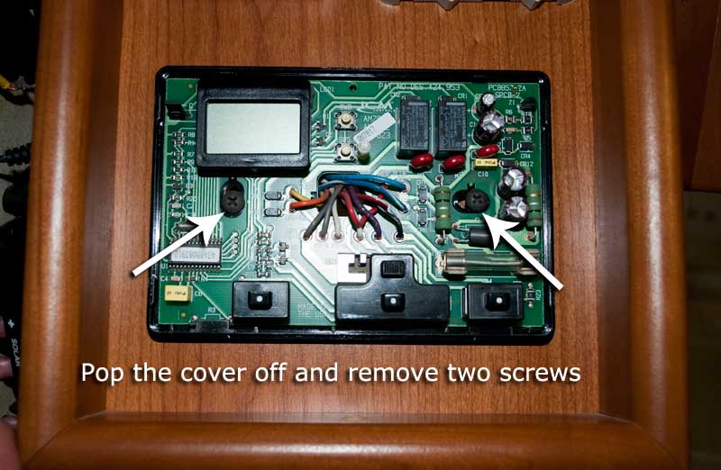
First off, let's remove this albatross
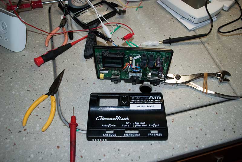
Dissecting and testing the Coleman-Mach thermostat
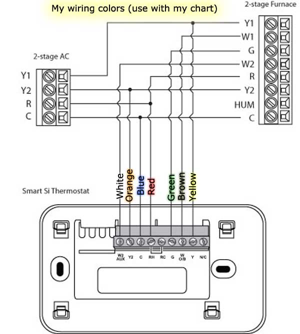
Above is how I wired up my Ecobee but the wire colors are the solid conductor thermostat wire I bought and soldered to the stranded Coleman-Mach thermostat wiring
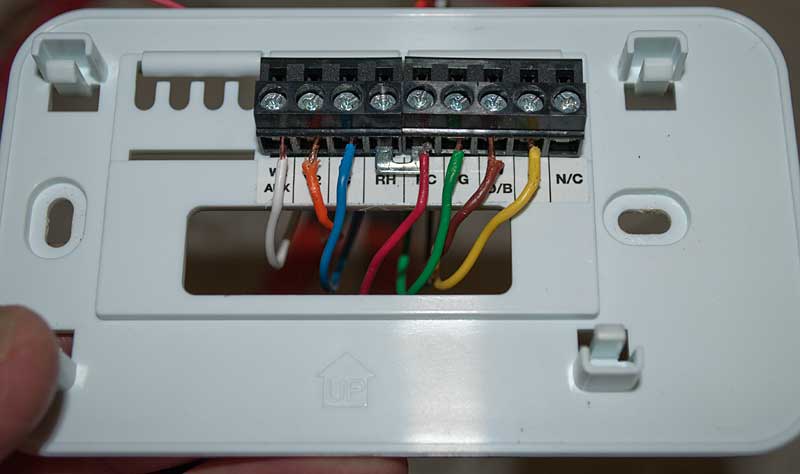
Just to reinforce the charts, etc - here's my actual back plate wiring
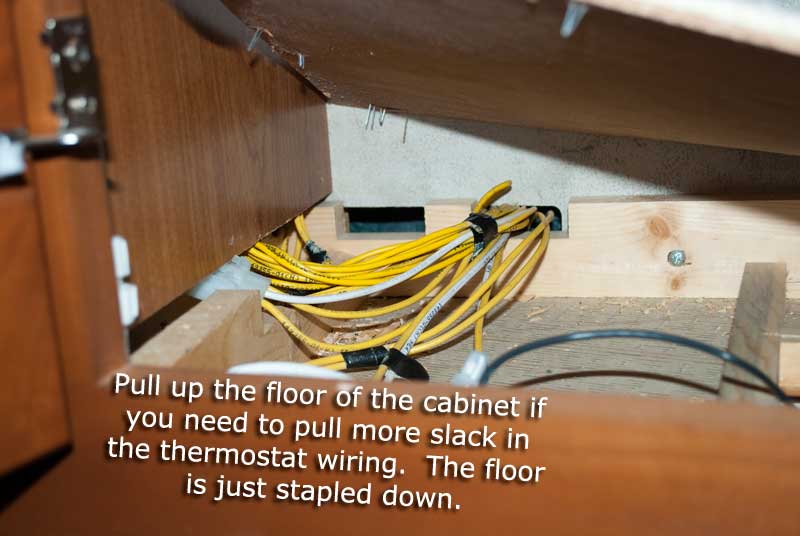
Pull up the floor (or whatever) to pull some wiring slack if necessary
Getting started on the wiring
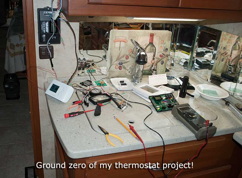
I made a mess but I cleaned it up :)
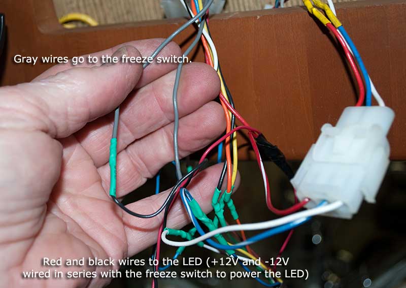
If you want to wire in an LED to the freeze switch, here's a few pictures that show what I did
Update Sept 5, 2016: The freeze switch LED idea never worked, the freeze switch never
dropped 12V to the LED. Either I don't understand the functionality of the freeze switch
or that particular switch never froze (and it might not be a mechanical switch, could be
a thermistor.)
Addendum December 2016! Some (myself included) have a problem when second stage heat is called (this would be the gas furnace) which causes the ecobee to reboot. I've suspected all along that the furnace was pulling the +12V source for the ecobee down so much the ecobee didn't have enough voltage to operate. The first solution I tried was a large value electroylitic capacitor (across red/+12V and blue/ground) which to my great surprise didn't solve the issue. So back to my earlier plan to pick up a better source of +12V for the ecobee.
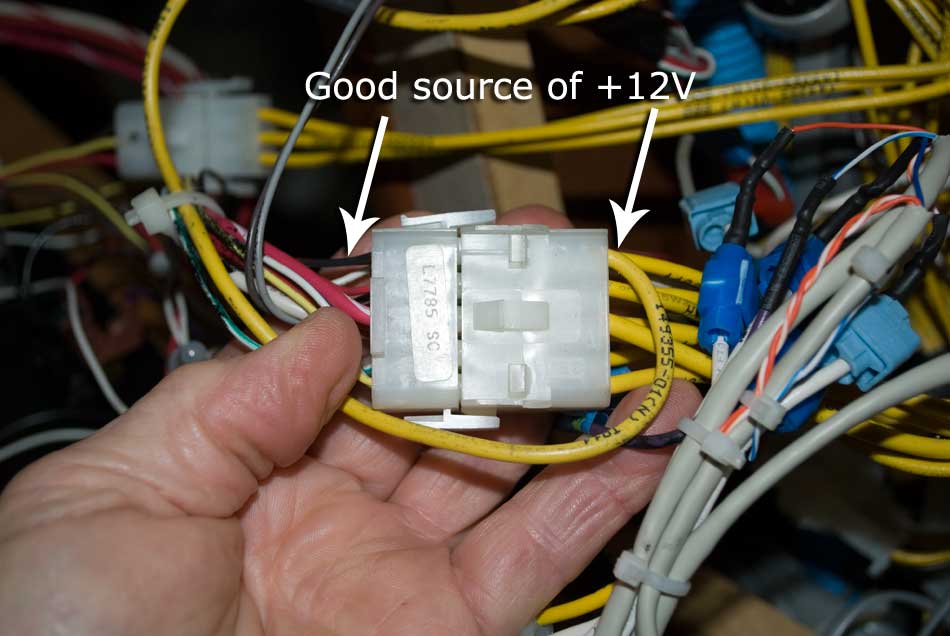
In the following two pictures I'll show you a good source of +12V to pickup and run over to the ecobee, add the extra wire from the new +12V source directly to the existing red wire on the back of the ecobee. You can tie in to either RC or RH on the back of the thermostat - whichever is easier.
Note in the picture that I'm pointing to is the rear of the voltmeter where you can read the house or chassis battery bank voltages.
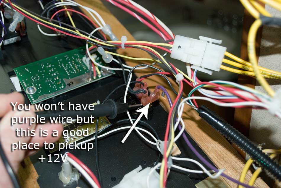
^^Reference the above picture^^ The other side of the small black wire (top left of the connector) is the +12V source I'm pointing to. The small black wire goes to the rear of the voltmeter as I've shown in the other picture.
And the finished install! Now let's set up the Ecobee Si Smart!
On to Page 3>>>>
<<<<Back to Page 1